F16 Sidestick - My DIY joystick for flight sims
![]() joystick_F16_sidestick @ Github
joystick_F16_sidestick @ Github
My F16 Sidestick
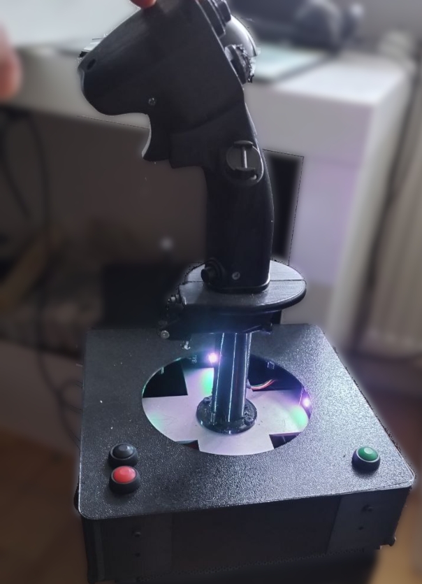
This repository holds (almost) all the information about my DIY F16 Force Sensing Sidestick I use mainly in DCS
The stick itself is printed from https://www.thingiverse.com/thing:4544115
I used different switches (navigation switches which I had laying around together with fitting PCBs. If those wouldn't have already existed in my drawer I would have used the switch designs included in the Thingiverse project.
My initial version was based on the well known olukelo gimbal with hall effect sensors, so I used the adapter I had on the gimbal for my force sensing approach too.
Components
beside the F16 Grip & Adapter
Mechanic components
Metal parts 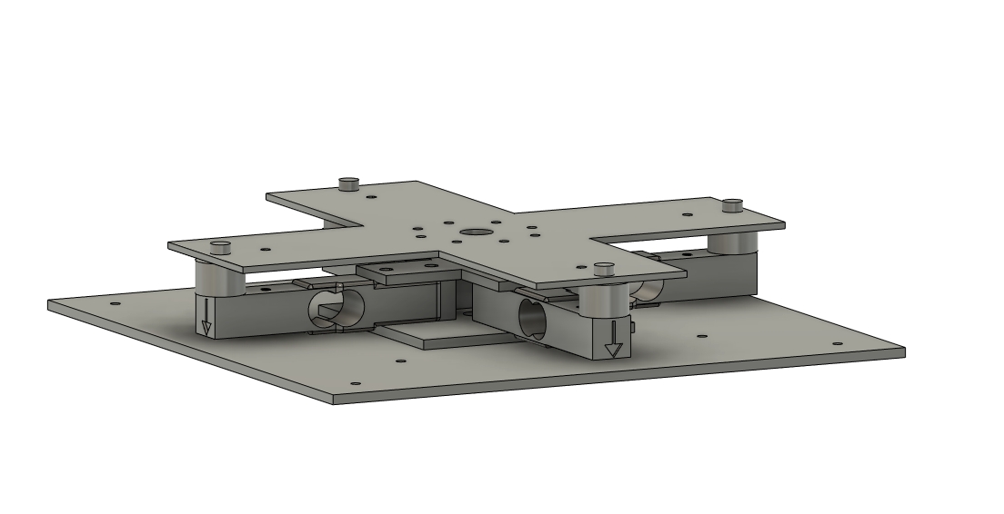
- 1x Ground plate (BodenPlatte.dxf)
- 1x Ground distance plate (BodenDist.dxf) - ensures distance between the load cells and the ground plate)
- 1x Top cross (Topkreuz.dxf) -connects the upper sides of the load cells in the center)
- 1x Top plate (Joyplate.dxf)
I ordered the aluminum parts at Xometry made out of 3mm sheets of EN AW-6060 / 3.3206 / Al-MgSi All 4 parts in the folder Hardware\Metal_parts together came with a total order value of 68.78 Euro
Other
- A unknown amount of M4 and M3 screws and nuts ;)
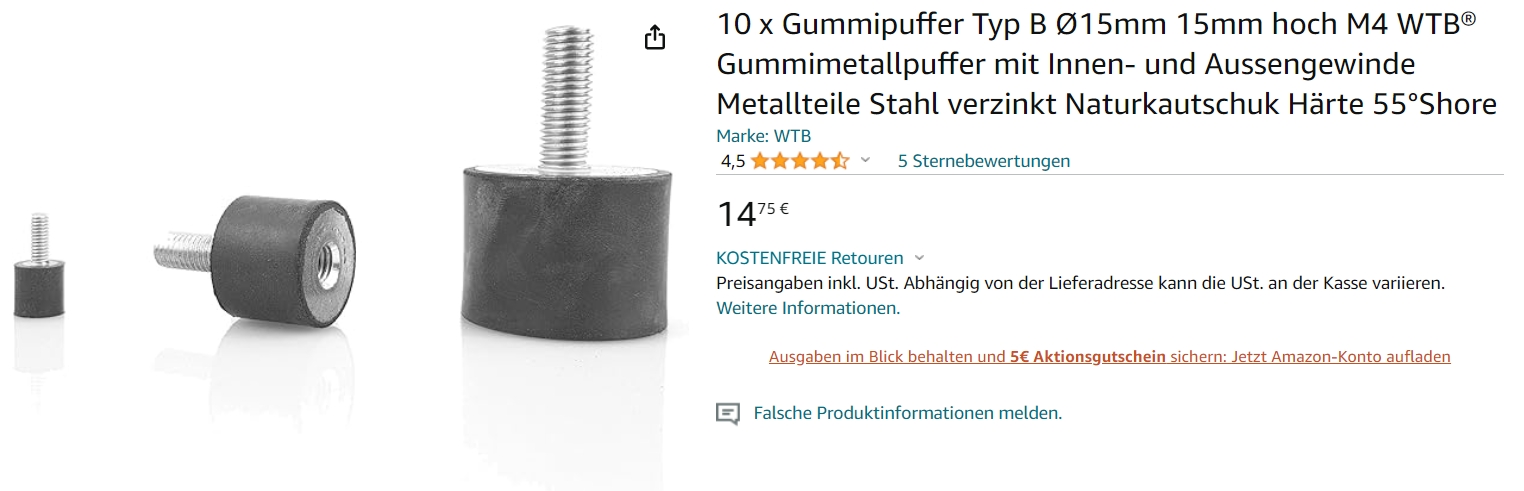
- 4 rubber buffers (15mm diameter, 15mm lenght, M4 screw thread
Load cells
- 4 x 80mm Load Cells (mine are 3kg, but that's personal preference). Be aware that there are 80mm and 75mm versions available, I designed it using the 80mm I already had at home
Case
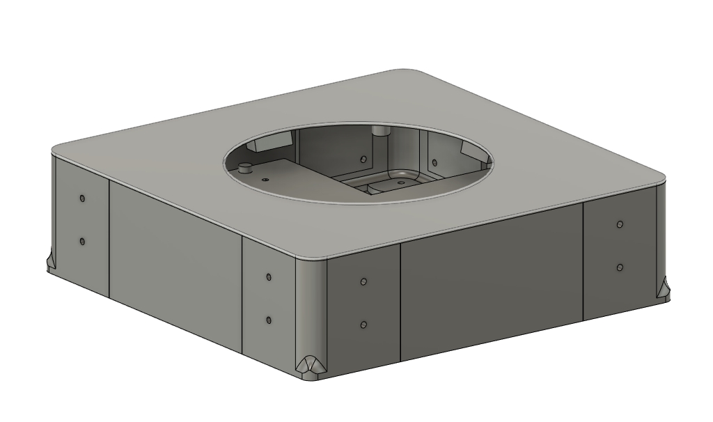 The case consists of
- 4 Side parts (Seiten_thin.stl - all 4 attached together)
- 4 Corners (Ecken_thin.stl- all 4 attached together)
- 1 Lid (Deckel_nd.stl)
The lid has small ramps to which I attached 4 WS2812B LEDs I cut from a strip I had laying around.
Electronics
-
Arduino Pro Micro (Clone) If you need to buy one, be sure to buy one with 5V (there are 3.3V and 5V available) and USB-C socket (the damn micro USB sockets are only SMD attached to the circuit boad and rip off easily)
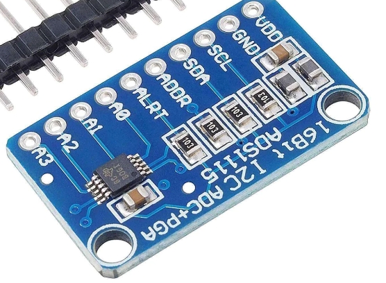
-
1x ADS1115 16bit ADC Modul for example by AZ delivery. But there are dozen other manucaturers which use the same board layout (ADS1115.jpg)
-
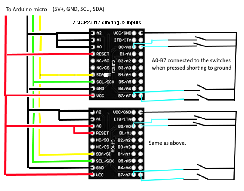
2x MCP 23017 IO Expander moduls
-
2x INA 122P instrument amplifier (I used sockets, but can be soldered directly to the PCB
-
1x Potentiometer >=10k type 3296 - 3/8 ? Square Trimpot
-
2x Potentiometer (same 3296 type, but 100 or 200 Ohm)
-
1x Base PCB That's the printed circuit board which holds all components in the base.
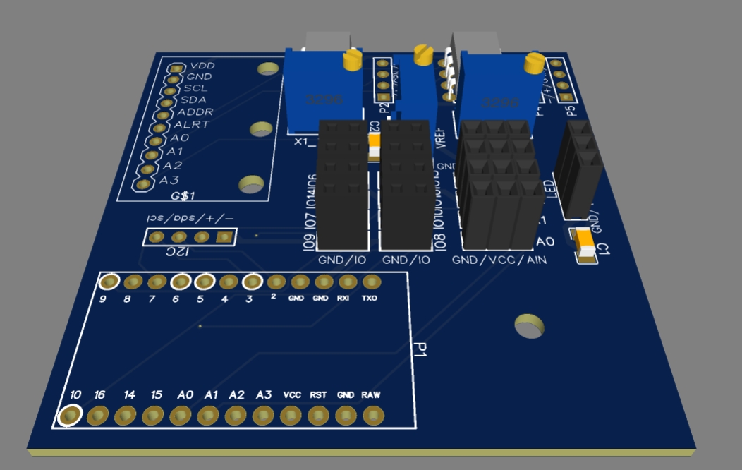 (the PCB has some additional ports, for up to 4 analog and 8 digital inputs, I connected 3 additional digital inputs to buttons. One for recalibration of the center position and noise and 2 for ingame functions)
Stick internal wiring
Internally all the buttons in the stick are wired up to 2 MCP23017 boards (as shown in Wire-connection.png). That means I only have 4 wires going out of the joystick into my PCB